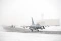
With a flashy black and yellow tail adorned with a skull and crossbones, the sleek fighter high above the US Air Force Research Laboratory at Rome in upstate New York is hard to miss. This aircraft, which is not actually an aircraft at all, is one of two full-scale models built by Lockheed Martin to measure the antenna performance of the F-35 Lightning II. The paint scheme mimics the insignia of VFA-103, the famed US Navy fighter squadron known as the Jolly Rogers.
Measuring F-35 antenna performance, or pole testing, began at Rome Research Lab eight years ago. The joint Lockheed Martin-F-35 Joint Program Office engineering team realized in the early stages of the F-35 program that a computer simulation could not adequately test the range, isolation, and overall performance of the aircraft’s antennas. And testing the antennas before the program finished building the first production aircraft was crucial.
“We needed to validate the antenna performance and ensure no major issues existed long before the first aircraft were finished,” said David Hamre, F-35 Radio Frequency Integration and Spectrum lead engineer for Lockheed Martin. “Continued testing allows us to tweak the design of the antennas and make modifications to the aircraft before full-rate production begins.”
By testing the F-35 antennas before the jet was flying, the team could determine if the antennas were meeting range and accuracy requirements, likely avoiding serious, and potentially costly, design modifications. The team of engineers quickly determined that, to get the data they needed before an actual F-35 was produced, they would have to build an exact replica of the jet, install the antennas, and begin testing antenna performance.
The team went to work constructing the first model – an F-35 frame that would represent both the F-35A conventional takeoff and landing, or CTOL, and short takeoff and vertical landing, or STOVL, variants. The fiberglass and aluminum frame was subcontracted to ATI and designed so that different antennas can be installed at various positions to validate and test gain patterns and performance. The team completed the model, replete with traditional Air Force markings and unique crest of the Air Force Research Lab Test Directorate, in ten months. Testing began in 2004 – a full two years before the first flight of F-35 AA-1, the first test aircraft.
Once the joint Lockheed Martin-USAF JPO team completed the model, the first sets of antennas were installed. The 8,500-pound model was then hoisted atop the fifty-foot tower to begin testing. In its new location, the model is put through thousands of antenna pattern tests to determine if each antenna is working as predicted by the design team.
“The model will stay up there for weeks or even months at a time,” Hamre said. “We wire it for multiple antennas – normally four to six different sets of antennas – and walk through all sorts of tests. We even roll the model upside down to test the antenna function when the aircraft is inverted.”
During the first few rounds of testing, a fixed antenna 5,000 feet away continuously radiated the CTOL model while the model was tilted and spun 360 degrees. By placing the model fifty feet above the ground and rotating it, the engineering team can get an accurate spherical picture of how the antennas operated from different angles. The team could then ensure the antennas would still function properly during rolls and maneuvering. The engineers then used antenna gain patterns to verify antenna positioning to determine if the antennas were blocked or obscured by the vertical tails. Antenna gain patterns could also verify if the aircraft emitted any unwanted reflections.
During some of the early testing, the team found an undesired reflection off the aircraft’s surface that needed to be corrected through a physical antenna redesign. Mission Systems engineers made changes in the design, tested those changes on the model, and ensured antenna performance was achieved before feeding the engineering changes into the F-35 production line.
“Without testing antennas on these models before the F-35 production began, we wouldn’t have found performance issues until flight tests were conducted many years later,” Hamre said. “These models saved us from having to retrofit antennas and from making serious changes after the aircraft were deployed.”
After the initial testing was complete, the team continued to use the CTOL model to isolate antennas, verify range requirements, and test antenna switching patterns.
“At any given time we may have upwards of twenty antennas on the airframe,” continued Hamre. “We need to see how much energy these antennas are putting into each other so we can have simultaneous operations of systems without interference. We were able to use this data to determine when to switch to different antennas and to validate how the antennas were working to design.”
Testing the CTOL model was a continuous process; the team completed tests as new antennas became available and as the program needed new information. With the majority of the CTOL testing now complete, Hamre and his team began constructing an F-35C carrier variant model to test how the larger wings and slightly different airframe may impact the aircraft’s additional antennas.
Perched atop the pattern tower since May 2012, the Jolly Roger CV model has completed most of its right-side-up testing. It is now undergoing inverted testing, which is scheduled to be completed by late 2013.
“Testing the CV won’t take as long because most of the basic testing was already done during previous tests on the CTOL model,” Hamre said. “With the CV, we are trying to characterize the larger wing and tail surfaces to see how obscuration is impacted. So far all of the antennas have been working as predicted.”
Over the past eight years, the team has compiled more than 1.5 million pattern files, verified multiple antenna positions, and made pre-production design modifications to ensure the early production models have the final features and capabilities. The models aren’t done making an impact just yet. As the program continues to grow and more F-35s are produced and flying, the CTOL and CV models will continue to perch atop the tower in upstate New York testing antenna patterns and performance of F-35s for international operators.
Sarah Shenk is a communications representative for Lockheed Martin.


 F-16 MATV Final Flight
 RIAT Report
 Viper Strong
 YF-16 First Flight (Flight 0)
 F-16 At 2013 Dubai Airshow
 F-16 Living Legacy
 F-16 Training, Texas Style
 F-16 Performs At 2011 Paris Airshow