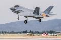
F-35B, however, thrust becomes the primary source of controlling flight.</p>")


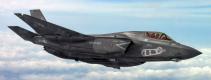
 and the redesigned inlet (shown here and called the flight inlet) are imperceptible to an untrained eye.</p>")


The C12 engine test stand rises above the flat Florida terrain like a massive metal insect. Five steel pipes, up to eight feet in diameter, connect at a central arm that supports the vertical lift system that will power the F-35B Lightning II. The structure rises high above the cooling ponds at the Pratt & Whitney Florida test site in West Palm Beach.
"We put about three million pounds of concrete and steel reinforcements in the C12 stand bringing the weight of the stand to about five million pounds to improve the accuracy of the thrust measurements," explains Gordon Boggie, who manages system engineering and validation for Pratt & Whitney at the Florida test site. "We had to add four legs to the structure to raise the natural frequency of the stand during engine runs."
One engine run will convince any visitor of the necessity for the additional bracing. In full-power afterburner, the F135-PW-100 emits a blue flame and generates up to 40,000 pounds of thrust. The exhaust sends whitecaps rippling across the nearby cooling pond and sways pine trees standing more than a hundred yards away.
"Without the reinforcement," continues Boggie, "the stand would oscillate slightly and affect our measurements." Accuracy of 0.5 percent for a 40,000-pound thrust class engine equates to 200 pounds. According to Boggie, the test setup is well within that margin of error.
Such accuracy is not always as critical when testing a typical commercial or military aircraft engine. For these powerplants, plus or minus two hundred pounds is inconsequential. Besides, these engines play a relatively small part in the flight control system. In vertical flight modes for the short takeoff/vertical landing (STOVL) F-35B, however, thrust becomes the primary source of controlling flight. An extra 200 pounds in the wrong direction can mean the difference between stability and its opposite.
"We're not just testing an engine, we are developing a STOVL propulsion system," Boggie explains. "The C12 test stand as well as the C14 stand next to it accurately measures forces in six axes: pitch, roll, yaw, vertical, lateral, and axial. The data taken from these system tests is used to refine the flight control software for the STOVL version of the F-35."
F-35B Vertical Lift System Explained
The STOVL propulsion system on the F-35B includes a lift fan behind the cockpit, roll posts on the underside of the wings, and a three-bearing swivel exhaust nozzle on the engine.
The lift fan provides almost half of the downward thrust needed for a pure hover mode. The fan's two sets of counter-rotating blades are driven by a driveshaft connected to the face of the main engine fan. A clutch at the forward end of the driveshaft engages the lift fan. The lift fan, which is covered from above by an aft-hinged door, opens as the aircraft transitions to hover mode. Thrust is controlled by the speed of the lift fan, a set of variable inlet guide vanes that reside above the rotating blades of the lift fan, and by a device called a variable area vane box nozzle on the lower side of the fan. The vane box nozzle contains a set of six vanes (or louvers) that direct and control the amount of downward thrust emanating from the lift fan.
The two roll posts together contribute about ten percent of the downward thrust. More importantly, they are used to control aircraft attitude in the roll axis. The posts are at the exit end of a duct that taps into the fan section of the main engine. Thrust for the posts comes from cooler air that normally bypasses the engine's turbine section. The exhaust areas of the two roll posts can be varied independently. The posts, therefore, control roll by expelling different amounts of thrust between the port and starboard sides of the aircraft.
The remaining vertical thrust is provided by the three-bearing exhaust nozzle on the main engine. The nozzle can swivel ninety-five degrees downward from the horizontal for lift and pitch control. The nozzle can sweep approximately twelve degrees left or right for yaw control.
Engine Testing Roundup
Pratt & Whitney is planning to test a total of seven STOVL lift systems and at least five conventional engines by the end of the current system development and demonstration phase of the F-35 program, which is scheduled to end in 2012. Most of the Florida STOVL engine testing will be completed by the end of 2009.
That testing falls into three major categories: developmental, endurance, and altitude. Developmental testing verifies the design of the hardware. Stresses, pressures, and temperatures are confirmed against the intent of the design.
Endurance testing demonstrates the durability and the life expectancy of the hardware. One of the STOVL engines in Florida is experiencing more than seven years of operational use in about six months. During these tests, the engine is taken through duty cycles it will experience in typical flight test missions.
Altitude testing involves operating the engine at a wide range of pressures and temperatures, simulating sea-level to high-altitude conditions. While most of the altitude testing has taken place at Arnold Engineering Development Center in Tennessee, Pratt & Whitney is adding altitude testing to its facilities in Florida.
Development Testing In Detail
"Most of our development testing in Florida is associated with low speeds and low altitudes, the lower left-hand corner of the flight envelope," notes Mark Tracy, manager of test operations for Pratt & Whitney at the Florida test site. "We are mitigating the risk for the powered lift flight test program for F-35B. Our work here verifies that the propulsion system will produce the amount of downward thrust needed for a successful flight test program for the F-35B and later for a successful real-world operation."
Recent developmental testing in Florida has focused on a redesigned inlet shape for the lift fan to get more lift and performance and to reduce flow distortion at the face of the lift fan. "The inlet is at ninety degrees to the airflow, so it presents a unique situation," explains Tom Sylvester, a senior engineer for Lockheed Martin present for these particular tests. "We used traditional methods for the initial design, but they just don't work well for a lift fan inlet because of the short distance between the inlet lip and the face of the fan. Unlike more traditional inlets, the airflow doesn't settle out before it gets to the fan surface."
The differences between the original inlet (called the development inlet) and the redesigned inlet (called the flight inlet) are imperceptible to an untrained eye. "The lip of the new inlet is only slightly different — an inch or two wider on the sides and a little taller," Sylvester explains. "The fan itself didn't change, but the inlet door was re-contoured to close securely against the new shape."
Northrop Grumman produced a metal/composite model of the new inlet shape. The model includes an aerodynamic fairing that replicates the fuselage area around the inlet that affects airflow into the inlet. The C14 test stand structure was modified for this model, which was installed on the stand with the rest of the vertical lift system in March 2007.
The vertical lift system with the new inlet and door combination was put through 116 hours of testing. During these tests, a crosswind generator used for testing effects of crosswinds on commercial jet engines was set up next to the test stand. The performance of the new inlet design was evaluated in crosswind angles of ninety degrees and wind speeds up to thirty-five knots.
The testing reduced a lot of un-certainties. "The lift fan performed better than we predicted," Sylvester explains. "The thrust numbers needed for hover are there." The biggest success is the additional thrust achieved from going to the development inlet to the flight inlet. "We increased the thrust and reduced the distortion in the lift fan, which will improve the durability and longevity of the system."
"The results were excellent," says Fran Ketter, research engineering director for Lockheed Martin and the program management interface for F-35 propulsion integration. "The inlet redesign resulted in significant improvements."
The performance achieved with this design meets the requirements and exceeds it in some areas. Just as important, the amount of thrust developed from the installed vertical lift system is now a known quantity. "That's a number we didn't have for the X-35B until that airplane did its first press up on the hover pad in California," continues Ketter. "We know that the lift system is going to produce adequate thrust margins and that we will be able to do everything planned for the upcoming flight test program for the F-35B."


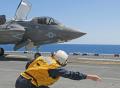
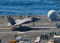
 F-35C DT-2 Aboard USS Eisenhower (CVN-69)
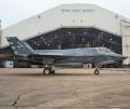
 F-35A First Flight In Italy
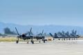
 F-35 Operations At Luke AFB
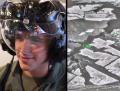
 F-35 Climatic Testing
 F-35 Pro Bowl Flyover
 First F-35C Lightning II Carrier Landing
 F-35 Program Video Update
 "With The Gear" Meets F-35
 Wet Runway And Crosswind Testing
 Australian F-35 Roll Out Ceremony