. The production F135 engine produces more than 40,000 pounds of thrust (uninstalled, at sea-level static conditions). The F135 engine shares a common core to the F119 but has a higher bypass ratio. Currently, the program is testing propulsion systems from two manufacturers: the F135 from Pratt & Whitney and the F136 from the General Electric Rolls-Royce Fighter Engine Team. The F-35s have been designed to accept either engine as part of the program requirement for engine interchangeability.</p>")


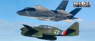
A side-by-side comparison of the X-35 Joint Strike Fighter prototype with the F-35 Lightning II production aircraft underscores the huge strides the JSF program has made transitioning from demonstration to development. The X-35 demonstrators, built and flown during the concept development phase of the program in 2000–2001, validated specific propulsion and design features incorporated on today’s F-35 Lightning II.
The most important part of the demonstration for the X-35B (the short takeoff/vertical landing, or STOVL, variant shown in the illustrations here) was the integration and operation of the STOVL propulsion system. The X-35B proved the viability of the shaft-driven lift fan and the performance available in STOVL. It also proved the viability of up-and-away flight. The demonstration culminated in the successful completion of “Mission X” on 20 July 2001. This mission combined a short takeoff, acceleration to supersonic flight, and a vertical landing in a single flight. Mission X demonstrated the integration of a STOVL lift system into a high-performance fighter.
The X-35 demonstrators, by any standard, were much simpler than the F-35 Lightning IIs that will be rolling out of the Lockheed Martin factory in Fort Worth, Texas. The demonstrators, for example, used a number of off-the-shelf components to speed design and fabrication. The fast pace of the program meant that only essential functions and capabilities were provided and tested. For instance, the X aircraft did not carry or drop weapons or include mission avionics. The demonstrators also did not carry signature treatments.
Still, the production versions maintain a strong family resemblance to their predecessors. The basic shape and layout are the same. The wing sweep angles for the leading and trailing edges are identical. (The F-35C has a much larger wing to improve low-speed handling characteristics for carrier landings, but the sweep angle is the same. The X-35C also had larger wings and tails than the X-35A/B.) The fundamentals of the shaft-driven lift fan system for the STOVL variant remain unchanged as well, which includes keeping the original three-bearing swivel nozzle. However, at a more detailed level, the production versions are different in every respect—from the tips of their noses, to their internal structures, to the angular feathers on their engine nozzles.
The demonstrators have been transformed into operational fighters during the current System Design and Development phase of the program. The cockpit has been refined. Full avionics functionality has been added. Engine thrust has increased. Capability and durability of the lift system have been improved. Internal weapon bays, radar, targeting system, and low-observable treatments are functional. New technologies that didn’t actually fly on the demonstrators—such as the electrohydrostatic actuators, integrated power package, or IPP, and helmet-mounted display—now function as integral parts of the F-35.
Many changes aren’t visible in the accompanying graphics. The highly automated manufacturing process used for the production versions is entirely different from the mostly hand-built process used for the prototypes. The internal structure has been redesigned to reduce weight and accommodate operational systems. Internal systems themselves have been added, redesigned, and moved around to reduce weight and cost, improve survivability, and make the aircraft easier to maintain. The aircraft has integrated prognostic and health monitoring sensors built into critical systems. These systems are part of a larger autonomic logistics system that will be used to support the aircraft in the field.
We have chosen to compare the X-35B and F-35B aircraft to highlight the extensive refinements. Most of the changes described here, with the exception of those related to the vertical lift system, apply to the other Lightning II variants—the conventional takeoff and landing, or CTOL, F-35A and the carrier variant F-35C.
The X-35 canopy was a two-piece, side-opening design with a conventional bow frame. The F-35 is a one-piece, forward-opening design with an integrated bow frame. The change improves signature characteristics while maintaining low weight. The bow frame was moved back slightly to improve visibility.
The X-35 had no radar. All F-35 variants have the Northrop Grumman AN/APG-81 with an active electronically scanned array that enables the F-35 pilot to engage air and ground targets at long range. The radar provides outstanding situational awareness for enhanced survivability. The AN/APG-81 builds on Northrop Grumman’s F-16 and F-22 radar heritage. Solid-state technology and the elimination of mechanical moving parts enable the radar to far surpass current standards for reliability. The radar system is designed for faster and easier repairs or upgrades to hardware and software modules.
The X-35 had two doors on the nose landing gear bay arranged fore and aft. The forward door looked and operated like the single large door on AA-1, the first F-35A test vehicle. The aft door was a slave door mounted to the strut perpendicular to the air flow. The F-35 has two smaller split doors. The split design increases control during landings in crosswinds and allows the vertical tails to be made smaller, saving overall aircraft weight.
The engine inlet changed from a four-sided shape to a three-sided cowl shape, while retaining the diverterless design. The original four-sided shape was derived from the diverterless concept tested on an F-16. The redesigned shape improves high angle-of-attack performance. Moving the inlets aft by thirty inches reduced overall aircraft weight.
The X-35B had a US Air Force type aerial refueling receptacle borrowed from the F-16. The F-35B and F-35C have an aerial refueling probe on the right side of the forward fuselage. The change accommodates the probe-and-drogue style refueling method used by the USMC and USN, and Royal Air Force and Royal Navy aircraft. The F-35A uses an aerial refueling receptacle similar to that of the F-22.
The nose boom on the X-35, which carried external pitch and yaw vanes carefully calibrated for flight test data collection, was connected directly into the flight control system. Under most conditions, the flight control computers used air data from the nose boom to fly the airplane. The F-35 has no nose boom and uses small fixed air data probes similar to those on the F-22. The flight science jets have nose booms, but they are not connected with the aircraft flight controls. The boom serves as a calibration source for production air data probes and static ports.
Overall length from the demonstrators to the production aircraft increased seven inches. The additional length, mostly in the forward fuselage, made room for equipment installation.
The total volume of the aircraft increased to accommodate weapon bays and additional internal equipment and fuel.
The auxiliary inlet provides an additional source for low distortion air for the engine during powered lift operation. When open at slow speeds, about sixty percent of the air at the engine face comes from the auxiliary inlet. The X-35B had a smaller opening with two doors hinged on the centerline of the aircraft. The F-35B has two doors hinged on the outboard sides of the opening. The change improves inlet flow performance. The increased size reflects the largest inlet within the structural constraints of the aircraft.
The horizontal tail area was increased slightly from the X-35B to the F-35B, and the aspect ratio was reduced to save weight. (Aspect ratio is the proportion of the long side to the short side of a wing. Long and skinny wings have high aspect ratios.) For better low-speed control, the F-35C has larger horizontal tail surfaces than the F-35A/B variants. Similarly, the X-35C also had larger horizontal tails.
The vertical tails are more upright with an increased aspect ratio and sweep. The rudder area was increased as well. Reducing the cant angle and changing the sweep made the tails smaller and lighter and improved supersonic directional stability. Increasing the rudder size improved control.
For the F-35B, wingspan increased from thirty-three feet to thirty-five feet, increasing the wing area from 450 square feet to 460 square feet. The change improved both takeoff and up-and-away performance. The increased span is compatible with US aircraft carriers and the new British carriers.
The X-35B used conventional hydraulic flight control actuators. The hydraulic pumps for both X-35s were salvaged from the YF-23 prototypes in storage at Edwards AFB. The F-35 uses state-of-the-art electrohydrostatic actuators for improved reliability and serviceability.
The X-35 carried a conventional auxiliary power unit on the forward right-hand side that provided power for engine starts. It also served as an emergency power source. The F-35 uses a unique integrated power package that provides emergency power and engine start capability as well as providing cooling air and cooling fluid.
The X-35 used environmental control system, or ECS, packs from the F/A-18 with heat exchanger scoops on the left side of the fuselage and under the wing. An additional heat exchanger was mounted on the belly of the X-35B during the flight test phase to provide cooling for hydraulic system oil. The demonstrators had ram air scoops that fed cooling air through the heat exchangers in the roll post bays for the X-35 aircraft or centerline heat exchanger for X-35B (shown here). The F-35 integrated power package, or IPP, provides the legacy ECS functionality, providing conditioned air and liquid cooling to aircraft systems. A unique feature of the F-35 cooling system is the integration of the IPP with the engine using engine fan-duct heat exchangers as a cooling source to the hot air side of the IPP. The F-35 environmental control system uses both fuel and air as a cooling medium. The fuel/air heat exchanger, located on the right top of the wing-glove, features a scoop inlet and screened exhaust.
The distributed aperture system (on the F-35 only) consists of six high-resolution, dual-band cameras that provide infrared and visual imagery from all spherical angles around the aircraft. The DAS takes the place of night vision goggles. The system increases situational awareness in flight and acts as a landing aid in low visibility.
The lift fan nozzle changed from a segmented extending hood to a variable area vane box nozzle. Although the variable area vane box nozzle does not provide as great a vectoring capability, it can save weight by being incorporated in a much more structurally efficient manner. Even more important than the weight savings, the variable area vane box nozzle allows greater flow control by using independently controlled vanes to control exit area and nozzle vector angle. The vane box design increases both lift fan thrust and overall system thrust for greatly improved lift capability.
The X-35 had several external heat exchangers. A nose ram air inlet was incorporated for backup avionics cooling. A centerline heat exchanger provided cooling for the hydraulic system. A heat exchanger on the left side supported the environmental control system. The F-35 has two scoops located in the wing/fuselage to provide nacelle bay ventilation. The aircraft also has a scoop located on the top of the right wing-glove to provide air to the fuel/air heat exchanger. A deployable scoop is located on the left-aft fuselage to provide air to the IPP and to the avionics. The F-35 minimizes the need for external scoops by using heat exchangers that are integrated in the engine fan duct. These heat exchangers use engine bypass air as a heat sink.
The X-35B had butterfly valves at the interface between the engine and the ducts leading to the roll nozzles. These valves were removed to save weight. The roll nozzles themselves now serve as the cutoff valves for the roll control air from the engine. The performance requirements for the F-35B roll nozzles are also greater because they have to deal with asymmetric external store loads.
The X-35B had no doors over the roll post nozzles. The doors were added to the F-35B to cover the roll posts and to reduce signature in up-and-away flight.
The production aircraft has a faceted housing between the radome and the nose landing gear that covers the electro-optical targeting system. The EOTS provides targeting information and laser designation capability to the helmet-mounted display.
The X-35B used a nose landing gear from an F-15 and modified main landing gear from a Navy A-6. The production F-35 landing gear is a new design tailored to STOVL operations to minimize weight. The retraction of the main landing gear is tightly constrained to clear both the internal weapon bay and the external stores.
The X-35 had a hydraulically operated speed brake on the underside of the fuselage immediately ahead of the doors of the three-bearing nozzle. On the F-35, speed brake functionality is provided through the use of the rudders and leading- and trailing-edge flaps.
The X-35 had no external store stations. The F-35 has seven external store stations that can carry all types of air-to-air and air-to-ground weapons, launchers, fuel tanks, and pods. The ordnance capacity is approximately 15,000 pounds for the F-35B and 17,000 pounds for F-35A/C. (Stations 2 and 10 are rated 1,000-pound stores for F-35B and 2,000-pound stores on F-35A/C.)
The X-35 had no need for weapon bays, which allowed that volume to be used to stow the main landing gear. The F-35 has large weapon bays capable of carrying two AIM-120 missiles and two satellite-guided JDAMs. The volume of the F-35A/C bays is slightly larger than that of the F-35B.
The inboard weapon bay doors serve a dual purpose. In addition to opening ninety-seven degrees for launching AMRAAMs, the doors are also used in vertical landing mode. The air flow from the lift fan and the aft nozzle flow meet and form a fountain below the airplane, so the weapon bay doors are opened to about forty-five degrees to form side walls to trap that fountain of air. Using the doors in this way increases vertical lift by ten percent at no additional weight. The X-35 had no such doors, but the concept was tested on the large-scale powered model during the concept development program.
The X-35B used a modified Pratt & Whitney F119 engine, with a new low-pressure fan and turbine, designated as the F119-611, which produced 38,000 pounds of thrust (uninstalled, at sea-level static conditions). The production F135 engine produces more than 40,000 pounds of thrust (uninstalled, at sea-level static conditions). The F135 engine shares a common core to the F119 but has a higher bypass ratio. Currently, the program is testing propulsion systems from two manufacturers: the F135 from Pratt & Whitney and the F136 from the General Electric Rolls-Royce Fighter Engine Team. The F-35s have been designed to accept either engine as part of the program requirement for engine interchangeability.
The engine nozzle was lengthened, and the production design was modified to incorporate serrated flaps. The nozzle used on the X-35 was quite short to provide ground clearance for STOVL modes. The increased nozzle length improved engine performance and reduced external drag. The serrated flaps improved aircraft signature. The engine nozzle on the F-35B is slightly shorter than the nozzle on the F-35A and F-35C.
The X-35 had a head-up display, or HUD, and two six- by eight-inch color displays from a C-130 for navigation, controls, and caution displays. The F-35 cockpit features a large eight- by twenty-inch multifunction color touch-screen display that can be customized and subdivided into many different-sized screens. A virtual HUD is projected onto the visor of the helmet-mounted display, or HMD, which performs other functions as well.
The production F-35 does not have a conventional HUD. Instead the pilot receives all the information through an HMD that would typically be seen through the HUD. The HMD is coupled to the EOTS and to a distributed aperture system.
The X-35 used modified side-stick and throttle controllers borrowed from the F-16. The X-35B had a separate nozzle lever for the pilot to control the angle of the propulsion system thrust in STOVL flight mode. The F-35 has unique controllers with active inceptors that provide feedback based on flying conditions. It has no separate controller for vertical flight. Instead, it uses the active inceptors to control aircraft acceleration both vertically and horizontally. The F-35 cockpit also makes use of voice recognition for commanding non-flight critical cockpit procedures, such as changing radio frequencies and inputting navigation coordinates.