over quality (sophistication and complexity).</p>")


 that bolt on the side of the fuselage on a nice clean planar surface. This construction method allowed other wing planforms (spans or sweeps) to be substituted later.</p>")


 stability. Flight operation with an unstable, highly controllable, free airframe was practical. Relaxed stability made the YF-16 more maneuverable.</p>")


 for the desired flight condition.</p>")

 were all evaluated in the design evolution of the YF-16.</p>")


 under the Director of Prototypes (Col. Lyle Cameron who led the original prototype screening team) at the Aeronautical Systems Division, Wright-Patterson AFB, Ohio (known as the Systems Project Office, or SPO). The Air Force Flight Test Center (AFFTC), Edwards AFB, was the responsible test organization. Though this arrangement was not particularly unusual, the relationship between the various test organizations and the SPO, was. There were two Joint Test Teams (one for the F -16 and one for the F-17), each consisting of a contractor, the Air Force Flight Test Center, and the TAC, NASA, and Air Force Test and Evaluation Center (AFTEC) members. The head of both test teams was the AFFTC Joint Test Force Director.</p>")


The concept of a low-cost, high-performance fighter evolved as a consequence of the marginal air-to-air combat effectiveness experienced by US fighters in Vietnam against small fighters such as the Russian-designed and built MiG-17 and MiG-21. In 1965, the combat exchange ratio, at best, was 3.3 to 1 compared to 10 to 1 during the Korean War. Later on, the exchange ratio decayed to slightly better than 1.5 to 1, which, to a large extent, was the result of a shift in emphasis to early generation air-to-air missiles and away from aircraft maneuverability.
The US Air Force attempted to counter these trends with a program called the Advanced Day Fighter, or ADF, which had the goal of developing a 25,000-pound fighter with a thrust-to-weight ratio and wing loading sufficiently high enough to maintain a twenty-five percent superiority over the MiG-21. About the same time, Col. John Boyd developed his theory of Energy Maneuverability with particular emphasis on smaller, more maneuverable fighters. The ADF program, combined with Boyd’s efforts, led to an even more aggressive program for reducing the size and improving the combat maneuverability of fighter aircraft—the Lightweight Fighter, or LWF, program.
The political rationale for the LWF was to have an airplane that would complement the McDonnell Douglas F-15. The LWF design objectives were to maximize usable maneuverability and agility in the air combat arena at a minimum of 500 nautical miles from base. This objective was to be achieved within the constraints of system cost, complexity, and utility. To this end, emphasis was placed on small size, low weight, low cost, advanced technologies, and aerodynamic innovations.
The Air Force request for proposals for the LWF program was released to nine aerospace manufacturers on 6 January 1972. The RFP was short, just twenty-one pages, and contained performance and cost goals, but very few traditional design specifications.
RFP responses were limited to a maximum of fifty pages to describe the aircraft and test program plus ten pages to address cost and management. Each response was to include wind tunnel data and a scale model for further wind tunnel testing. The initial competition was, in effect, a wind tunnel flyoff and proposal evaluation.
General requirements in the RFP included a high thrust-to-weight ratio, good transonic maneuverability, a simple avionics and fire control system, a minimum load factor of 6.5 g, a suggested gross weight of 20,000 pounds, and a suggested unit flyaway cost of no more than $3 million (in 1972 dollars and based on a buy of 300 aircraft at a rate of 100 aircraft per year). Five of the nine companies responded: Boeing, General Dynamics, Lockheed, Northrop, and Vought.
The proposals were delivered to the Air Force on 18 February 1972. A preliminary analysis concluded that the Boeing Model 908-909 design was the number one contender. The General Dynamics Model 401 design was a close second. Northrop’s twin-engine Model P-600 design followed in third place. Vought’s Model V-1100 was fourth. The Lockheed Model CL-1200 Lancer design was a distant fifth.
On 18 March, the results were delivered to the Source Selection Authority headed by Lt. Gen. James Stewart, Commander of Air Force Systems Command’s Aeronautical Systems Division at Wright-Patterson AFB, Ohio.
Members of the Source Selection Authority board analyzed the findings of the preliminary analysis panel and, after some revision, determined the General Dynamics airplane to be the first choice. The Northrop airplane came in second, and the Boeing airplane third.
The SSA’s conclusion was partly based on the fact that the General Dynamics and Boeing proposals were very similar; thus to satisfy one of the main objectives of the prototype concept (validation of emerging technologies on two different designs), the decision was made to award the second contract to Northrop instead of the Boeing design.
Air Force Secretary Robert Seamans made the final decision. Following a conference with Stewart and a further detailed analysis of the top three contenders, Seamans elected to proceed with the prototyping and flight testing of the General Dynamics and Northrop designs. Accordingly, General Dynamics was awarded $37,943,000 for two Model 401s. Northrop was awarded $39,878,715 for two Model 600s. The difference in the contract awards can be traced to the Northrop design having two engines.
The Test Program
The primary test objective of the next phase of the LWF program was to determine the potential operational usefulness of the LWF and its advanced technological features.
The test program was structured in several phases. First, predicted data would be verified as the test programs were planned. Aerodynamic details and avionic systems would be evaluated. Operational factors also weighed in on the evaluation. Performance and cost would determine the winner of the competition.
While General Dynamics and Northrop were given a free hand in the design and fabrication of their respective aircraft, the Air Force played the lead role in testing and evaluation.
Two joint test teams (one for the YF-16 and one for the YF-17) each consisted of members from the contractors, the Air Force Flight Test Center, Tactical Air Command, NASA, and the Air Force Test and Evaluation Center. The head of both test teams was the joint test force director from the Air Force Flight Test Center. Each test team was monitored by a test management council that consisted of the System Program Office, or SPO, and a director and senior representatives from the other organizations as well as the contractors.
The overall management of the LWF program was the responsibility of Col. Lyle Cameron, the director of prototypes for Prototype Program Office at Aeronautical Systems Division. (Cameron also led the original prototype screening team.)
The YF-16 Design
The General Dynamics Model 401, as the YF-16 was known in-house, was the product of a lengthy design study and wind tunnel test program that had been executed during the preliminary discussion days with John Boyd, test pilot and defense analyst Col. Everest Riccioni, and by the General Dynamics chief project engineer Harry Hillaker, who had guided the project through several years of low-level company support.
To perform the prototype contract, company vice president and program director Lyman Josephs and director of engineering William Dietz were assigned to the program in November 1971. Additionally, a total of 650 personnel participated in detail design and fabrication of the prototypes. The project was divided into twenty-eight work breakdown structure elements, with a manager responsible for engineering, tooling, fabrication, and assembly budget in each element.
The concept of the YF-16, as formulated by Hillaker, involved the prudent application of integrated advanced technologies and design innovations to achieve an aircraft that could satisfy the conflicting requirements of high performance and low cost. Emphasis was placed on small size and low weight in the selection of technologies to realize the best balance of combat capability (turn rate and acceleration) and lowest possible mission weight.
The key configuration elements that offered clear superiority in terms of maximum lift, directional stability, drag-at-lift, and propulsion performance were a bottom inlet, wing-body blending, variable camber wings, and a single vertical tail. Additionally, the YF-16 team determined that a single-engine configuration was nearly 4,500 pounds lighter than a twin-engine configuration (for a 500-nautical mile mission radius). Design tradeoffs of wing loading, thrust loading, specific excess power, combat radius, and fuel fraction were conducted to define the configuration providing the best combat performance for the lowest weight.
The decision to pursue small size and light weight ran counter to a widely held belief that small aircraft have no range and little payload capability. The argument was used by the Air Force in favor of the F-15 and against the LWF at times. However, this relationship of size to range was a misconception. As US fighters had gotten progressively larger through the years, the design (specification) mission radius had, in fact, gone down.
Historical trends aside, the YF-16 destroyed this misconception during the LWF flight evaluation, when the aircraft exhibited a specific range (nautical miles per pound of fuel) of 0.25 to 0.39, compared to 0.15 to 0.20 for the F-15A and 0.08 to 0.12 for the F-4E. Additionally, although smaller in size, the YF-16 had a higher fuel fraction (0.28) than the F-15 (0.25), which meant that the smaller YF-16—with better specific range and higher fuel fraction—had greater range than the larger F-15A.
Integrated Advanced Technologies
The YF-16 incorporated a number of advanced technologies that had not been used in previous operational fighters and, when coupled with design innovations, produced significant payoffs in terms of combat performance and cost.
The blended wing-body, or lifting body concept, was achieved through a smooth fairing between the wing and fuselage rather than the conventional angular intersection. This blending provided lift at high angles of attack. The thickening of the wing at the fuselage joint actually resulted in a weight savings of about 250 pounds.
The blending also results in a high volumetric efficiency. A conventional wing-body would require a foot-longer fuselage to get the same volume, adding to the structural weight.
In addition, blending made up for the cola-bottle effect of transonic drag area-rule by removing volume around the center of gravity right in the area where it is desirable to have volume for fuel, payload, and the main landing gear. Wind tunnel tests verified that wing-body blending did indeed provide increased lift with increasing angle of attack.
Controlled vortex flow proved to be the key to attaining maximum usable lift and excellent handling qualities for the YF-16. Sharp-edge forebody strakes, located on the forward fuselage ahead of the wing, generated strong vortices with increased angle of attack.
To generate the same amounts of lift, an equivalent wing without a strake would need both a higher aspect ratio and more area. Wind tunnel testing verified additional lift and a significant improvement in pitching moment. Similarly, the wind tunnel results verified the directional stability improvement and maneuvering at maximum lift with only mild buffet effects.
Automatic variable camber was the key to defining a wing planform that provided a balance between subsonic and supersonic maneuver conditions and acceleration while maintaining outstanding handling qualities and tracking precision throughout the Mach 0.8 to Mach 1.6 combat arena.
The use of leading-edge flaps is not new. In this instance, plain, single in-chord flaps were selected instead of slotted types because of their simplicity and because this flap could be used throughout the flight envelope and could be scheduled to provide the best flap position (camber) for the desired flight condition. The flaps were automatically programmed for best position/deflection as a function of Mach number and angle of attack.
Leading-edge-flap deflection reduced the pitching moment at high-lift coefficients, yielding much higher trimmed lift and lower trim drag for increased turn rates. For supersonic flight, the leading and trailing flaps were deflected up two degrees to reduce camber drag penalties. The flap control was tied-in with the gear retract handle so that the flaps were fixed in the takeoff and landing position when the gear was down and set to the automatic mode when the gear was retracted.
Perhaps the biggest step made in the application of advanced technology was the decision to use an all-electronic fly-by-wire flight control system instead of a conventional hydromechanical system with linkages and cables. The reduced lags and overshoots afforded by the better kinematics inherent in the fly-by-wire system resulted in greatly improved and expanded flying qualities.
The flight control system was a high-authority command and stability augmentation system. A roll-rate and g-command maximized response in the pitch and roll axes throughout the flight envelope. The g-command also provided constant stick force per g in the pitch axis. Static and dynamic stability augmentation was provided in the pitch and yaw axes, with damping augmentation in the roll and yaw axes. Spin/stall prevention was achieved through angle-of-attack limiting.
Turn coordination was provided through an aileron-rudder interconnect and a roll rate-to-rudder feedback. This arrangement improved turn performance at high angles of attack and reduced the risk of departures.
The high reliability and redundant features of the fly-by-wire flight control system’s stability augmentation made a relaxed static stability design possible. In a conventional configuration design approach, the center of gravity, or c.g., is generally located forward of the aerodynamic center, or a.c., to provide positive static stability. The horizontal tail deflection required to balance the moment resulting from this relationship causes trim drag and creates a down-load on the horizontal tail. The technique used in the YF-16 of locating c.g. aft of the a.c. allowed a reduced or negative static margin (relaxed static stability) in the longitudinal axis.
The advantage of this technique was that the horizontal tail size or the tail deflection angles required for high-g maneuvers and supersonic flight were reduced, with a resulting reduction in trim drag. In a highly maneuverable fighter, trim drag at high-g is a significant parameter.
In the YF-16, the trim drag at high load factors and at supersonic speeds was reduced by as much as fifty percent, which increased the supersonic turn rate by about fifteen percent and the subsonic turn rate by about eight percent. The reduced trim drag also reduced the mission weight by 400 pounds. When coupled with fly-by-wire, relaxed static stability produced a maneuvering airplane with more than twice the response of conventional fighters, which further enhanced its combat agility.
Lateral-directional stability is enhanced by the interaction of the forebody strake and the leading-edge-flap deflection. This interaction had a significant influence on the vertical tail configuration. Many single- and twin-tail variations—including tail size, planform, longitudinal location, and lateral location and cant angles for twin tails—were examined and wind tunnel tested.
Previously available wind tunnel data had indicated that twin tails would provide a higher level of directional stability, particularly in sideslip; however, this data was limited to fifteen-degrees angle of attack. Twin tails were sensitive to strake configuration and, therefore, constituted a greater development risk. The single vertical tail configuration not only provided the highest level of lateral-directional stability but also had the lowest exposed area, which resulted in lower structural weight and lower friction drag.
Although a number of aircraft had been flying with fixed, normal shock inlets, the expanded application of such an inlet into the high-transonic/supersonic region was not previously thought feasible or practical. The integration of inlet/cowl geometry, inlet placement, and duct length offered the potential of a simple, lightweight, low-cost inlet that was stall-free throughout the flight/maneuver envelope and had sufficient pressure recovery for a maximum speed of Mach 2.
A single, bottom-located, normal shock inlet was simpler, less costly, and significantly lower in weight and drag and resulted in higher overall maneuver potential than other inlet types. The fuselage shielding lowered the flow angularity at the inlet, which in turn allowed more of the maneuver potential of the airplane to be usable.
A bottom inlet did not necessarily present a foreign object damage, or FOD, problem. On the YF-16, the nose wheel location aft of the inlet face eliminated the prime cause of FOD. Although inlet suction while static (zero forward velocity) could induce FOD, the height of the inlet lower lip off the ground minimized such ingestion.
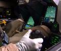
A specially tailored high-g cockpit provided the necessary man-machine interfaces for head-up, hands-on flight control and weapon delivery with unrestricted visibility and improved g tolerance. The crew station was configured so that the pilot can engage in air combat without removing his hands from the throttle and controller or his eyes from the target. In addition, he could perform his tracking and control functions effectively in high-g combat.
The thirty-degree reclined position with a raised heel-rest line was selected because it afforded a reasonable improvement in pilot g-tolerance level and tracking error while still retaining conventional and proven cockpit instruments, equipment, ejection seat, and arrangement criteria.
The application of fly-by-wire technology permitted the use of a minimum-displacement-force sensing sidestick controller. This configuration allowed more precise pilot inputs and minimized the possibility of inadvertent inputs and feedback, which were particularly critical during high-g maneuvers in the vertical and lateral directions.
Completely unobstructed visibility in the principal search area was provided by a one-piece canopy. A polycarbonate bubble canopy provided 360-degree upper hemisphere vision, with a minimum of fifteen degrees over the nose, forty degrees down at the ninety-degree azimuth, and excellent aft vision to cover the six-o’clock direction. A thirty-degree average slope of the windshield provided superior optical quality. Although the full bubble represented a significant supersonic drag penalty, the approach was consistent with eyeball-to-eyeball combat and with the high-maneuver capability of the airplane.
The avionics, cockpit, and armament subsystems were fully integrated to minimize pilot workload during all phases of weapon delivery. Critical fire control functions, such as the gun, missile, radar control, and weapons release, were located on the throttle and flight controller grips to provide quick-reaction, fingertip control of weapons and displays during all maneuvering conditions.
Wing planform selection was one of the most critical of the configuration decisions affecting the ability of the airplane to achieve maximum performance at lowest weight. Combat conditions for the LWF were prioritized into four categories: Mach 1.2 turns, Mach 0.9 turns, transonic acceleration, and maximum lift (defined at Mach 0.8 at 40,000 feet).
Four wing planform families (straight, swept, variable sweep, and delta) were examined. A low-sweep, nearly straight wing provided the most suitable performance. The specific geometry of the selected wing (forty-degree leading edge sweep) involved a trade of wing loading versus aspect ratio to achieve the best balance of turn rate and acceleration.
Recognizing that fighter aircraft always end up with external fuel tanks, Hillaker and his design team decided to use an internal-external fuel concept in the sizing approach. Sizing the aircraft at the start of combat on internal fuel (with combat fuel and return/reserve fuel) and using external fuel for the outbound leg reduced the size of the YF-16 by about 1,470 pounds weight empty and 3,300 pounds gross weight. This approach produced a five percent increase in turn rate and a thirty percent improvement in acceleration time.
The combination of engine cycle (bypass and pressure ratios) and number of engines was a significant parameter in determining the gross weight (mission weight) of the YF-16. During the initial conceptual phase of the LWF program, General Dynamics evaluated two engines with different bypass ratios. These were the Pratt & Whitney F100 turbofan with a bypass ratio of 0.72 and the General Electric YJ101 turbojet (not to be confused with the later GE F101 turbofan) with a bypass ratio of 0.20. The former was examined for use in single-engine designs, and the latter for twin-engine designs.
The two powerplants and their respective configurations were evaluated by comparing the combined engine and fuel weights required to accomplish the design missions including cruise, combat, and needed fuel reserves.
The YF-16 design mission included a 500-nautical mile high-subsonic cruise leg, a maximum afterburner acceleration, maximum afterburner subsonic and supersonic sustained turns, and a twenty-minute sea level reserve.
Hillaker and his design team concluded that a single F100 turbofan engine with its higher bypass ratio provided the best balance of combat capability and mission radius for the lowest weight. A basic configuration meeting the stated performance/mission goals could be achieved at a mission weight of 17,050 pounds, whereas twin GE YJ101 engines resulted in a mission weight of 21,470 pounds. A single GE YJ101 configuration was also examined to see how small an aircraft could be defined. However, the configuration could not meet performance and mission goals.
The structural criteria established for the YF-16 enhanced performance/mission capabilities beyond previous fighter designs. The YF-16 design load factor was established at nine g at full internal fuel as opposed to the traditional requirement of 7.33 g at eighty percent internal fuel. The service life was established as 8,000 hours instead of the normal 4,000. Although a basic part of the design rationale centered on minimum avionics, the design team recognized that future needs would likely demand more capability than initially planned. Thus, the avionics/subsystem architecture was defined to accept progressive improvement and growth in capacity and volume.
Configuration Variables Tested
Efficient, usable, high-energy maneuverability demands the total integration of the overall configuration. Before the YF-16 configuration was finalized, seventy-eight configuration variables having significant impact on the maximum usable maneuver potential had been thoroughly analyzed, evaluated, and wind tunnel tested. The configuration variables included:
- Conventional and blended wing-body shaping
- Leading-edge sweep angles of 35, 40, and 45 degrees
- Fixed and variable camber wings
- Six airfoil sections, including thickness, camber, and variations from root to tip
- Side inlets and bottom inlets with two different shapes on the bottom inlet
- Twin and single tails with varying planforms, areas, and location
- A complete family of forebody strakes, including canards
The wind tunnel tests devoted to evaluating these variables totaled 1,272 hours of running time.
Each of these advanced technologies, when integrated with the others, made a direct and relevant contribution to the specified mission and combat performance. Together these technology and design innovations produced the equivalent of a ten percent reduction in airframe weight. The lighter airframe resulted in both lower material cost and a twelve percent reduction in mission weight as well as increased performance through an increased thrust-to-weight ratio and lower drag (lower drag in terms of total pounds of drag). The cumulative benefits of these integrated technologies yielded a reduction in mission weight of 4,420 pounds (2,325 pounds in airframe weight and 2,095 pounds in fuel weight). At a rate of $350 per pound, this equated to at least $800,000 in reduced airframe cost.
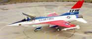
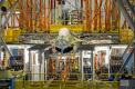
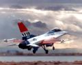
Following signing of the official contract on 13 April 1972 (which also called for some twelve months of flight testing), construction of the two prototype YF-16s was initiated. The aircraft were some twenty-one months in the construction stage (this being an exceptionally short gestation period for a high-performance, advanced-technology aircraft). The official taxi-out ceremonies with the first YF-16 (72-1567) took place on 13 December 1973 at General Dynamics production facility in Fort Worth, Texas.
The Flyoff
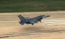
The first YF-16 was transported to Edwards AFB, California, on 8 January 1974 in the cargo compartment of a C-5. The YF-16 was inadvertently flown for the first time less than two weeks later. The first official flight came on 2 February. The Northrop design, designated P-600, rolled out on 4 April 1974 at Hawthorne, California. The YF-17 took off on its first flight at Edwards in June. The YF-16s were flown on 330 missions and logged 417 hours of flight time during the competition, which ended in December 1974. The YF-17s flew 268 flights and logged 324 hours.
Besides meeting the low-cost goal, the YF-16 met or exceeded all other USAF-established goals including those met by the YF-17. The YF-16 had a mission radius advantage over the YF-17 of 200 nautical miles, a sustained turn rate advantage of 0.5 degrees/second at Mach 1.2 at 30,000 feet, a fifteen-second advantage accelerating from Mach 0.9 to Mach 1.6 at 30,000 feet, and a ferry range advantage of 350 nautical miles. Air Force Deputy Chief of Staff for Research and Development, Lt. Gen. William Evans, noted the differences, “The YF-16 outperformed the YF-17 from the beginning of the flight test program. The YF-16’s maneuver energy, dash speed, turning rates, and handling qualities were all superior.”
On 13 January 1975, Secretary of the Air Force John McLucas declared the YF-16 the winner of the competition. Secretary of Defense James Schlesinger commented on the selection at the time: “It is a happy circumstance that the airplane with the best performance is also the lowest cost.”
Credits
This article was adapted from Chapter 6, “A Star Is Born,” from Aerograph 1: General Dynamics F-16 Fighting Falcon by Jay Miller, Aerofax, Inc., 1982. Special thanks to Kevin Renshaw for his technical review.


 F-16 MATV Final Flight
 RIAT Report
 Viper Strong
 YF-16 First Flight (Flight 0)
 F-16 At 2013 Dubai Airshow
 F-16 Living Legacy
 F-16 Training, Texas Style
 F-16 Performs At 2011 Paris Airshow